Knowledge
The Complete Guide to Fiber Optic Cable Management

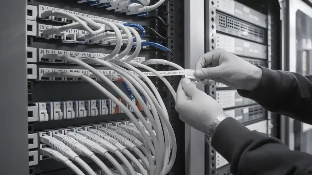
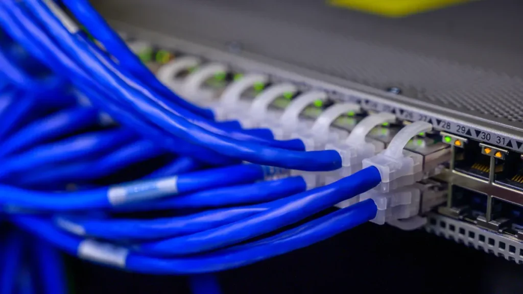
Effective fiber optic cable management helps you ensure stable networking and high-speed data transfer. As you work in the telecommunications field, you face complex challenges from rapid network growth and increasing data demands. Traditional methods can slow down your operations and increase the risk of errors. Digital tools, such as IQGeo’s Fiber Network Management System, now offer smarter Fiber Optic Solutions for tracking, organizing, and maintaining networking infrastructure.
Key Takeaways
-
Choose the right fiber optic cable type—single-mode for long distances and multi-mode for shorter runs—to match your network needs and budget.
-
Plan and document your fiber optic installation carefully to support current demands and future growth, saving time and money later.
-
Follow strict safety practices, including wearing protective gear and avoiding direct eye exposure to fiber light sources, to protect yourself and your team.
-
Combine digital tools like IQGeo’s Fiber Network Management System with physical cable management solutions for efficient, real-time network monitoring and organization.
-
Use proper cable management accessories such as cable managers, ties, trays, and raceways to prevent damage, maintain signal quality, and simplify maintenance.
-
Maintain the correct bend radius and crush protection during installation to avoid signal loss and costly repairs.
-
Test every fiber optic cable using industry standards and tools like OTDR and Visual Fault Locators to ensure reliable network performance.
-
Label and color-code cables clearly following industry standards to reduce errors, speed up troubleshooting, and support future upgrades.
Fundamentals
Establishing proper bend radius control, tension management protocols, and systematic organization forms the foundation of fiber management—implementing structured routing and labeling while executing proactive maintenance ensures network reliability.
Fiber Optic Cables
You work with fiber optic cables every day, but understanding their types and uses helps you make better decisions for your network. The two main types are single-mode and multi-mode fiber. Single-mode fiber has a small core (the light-carrying center) and transmits one mode of light, which allows you to send data over long distances with minimal signal loss. Multi-mode fiber has a larger core and carries multiple light modes, making it ideal for shorter connections, such as within data centers. Both types offer high bandwidth, immunity to electromagnetic interference, and lower power consumption compared to copper cables.
Here’s a quick comparison to help you choose the right cable for your needs:
|
Fiber Optic Cable Type |
Description |
Subtypes |
Typical Use Cases |
|---|---|---|---|
|
Single-mode fiber (SMF) |
Single glass strand, high bandwidth, long distance, higher cost |
OS1, OS2 |
Telecom, long-distance transmission |
|
Multi-mode fiber (MMF) |
Multiple glass strands, lower cost, limited distance/bandwidth |
OM1–OM5 |
Data centers, short connections |
|
Active Optical Cables (AOC) |
Built-in transceivers, easy deployment, space-saving |
N/A |
Compact data center connections |
You should select the fiber optic cable type based on your application, distance, and budget. For example, single-mode fiber works best for connecting buildings across a campus, while multi-mode fiber suits server racks inside a data center.
Boost Fiber Network Performance Nowerformance Today
25+ years expertise. IP68 termination boxes, bend-insensitive cables & smart tools ensure 99.99% uptime. 48-hour delivery, exclusive pricing—limited stock!
Key Principles
To ensure your fiber optic cable installation delivers reliable performance and lasts for years, you need to follow several key principles:
-
Plan and design your cabling with current and future bandwidth needs in mind.
-
Choose the right fiber type for each application.
-
Build redundancy into your network by using separate paths for critical connections.
-
Use proper installation techniques, such as maintaining the minimum bend radius and cleaning connectors.
-
Select high-quality components to prevent signal loss.
-
Label and document all cables for easy maintenance and troubleshooting.
-
Test every connection after installation to meet industry standards like TIA/EIA-568.
-
Schedule regular inspections and cleaning to maintain performance.
-
Monitor environmental factors, including temperature and vibration, that can affect fiber.
-
Stay updated with new technologies and standards.
-
Design your infrastructure to be modular and scalable for future upgrades.
Tip: Careful planning and documentation save you time and money during future expansions or repairs.
Safety
Working with fiber optic cable requires strict safety practices to protect yourself and your team. You must avoid direct eye exposure to fiber light sources, as invisible laser light can cause serious eye injuries. Always wear safety glasses and protective clothing to shield against glass shards and cable materials. Make sure your workspace has good ventilation to prevent inhaling tiny glass particles released during installation.
-
Never touch your face while handling fiber to avoid transferring glass fragments.
-
Remove flammable materials from the area, especially when using fusion splicers.
-
Use proper lubricants and handle strength members with care.
You must also comply with OSHA and other safety regulations. Management should train all personnel in safe practices and enforce the use of personal protective equipment (PPE) like hard hats, gloves, and high-visibility vests. Supervisors need to conduct risk assessments before starting work and maintain a site safety file with emergency plans and incident reports. When working near power lines or underground utilities, always follow established safety protocols and call utility location services before digging.
Note: Training and certification, such as FOA CFOT (Certified Fiber Optic Technician), help ensure you and your team work safely and effectively.
Fiber Optic Solutions
Modern fiber optic solutions help you manage complex networks and support high-speed data transmission. You need to choose the right mix of digital and physical tools to keep your fiber optic infrastructure organized, reliable, and ready for future growth. This section explains how digital and physical solutions work together to improve your fiber optic cable management.
Digital Solutions
Digital solutions have transformed how you plan, monitor, and maintain fiber optic networks. IQGeo’s Fiber Network Management System (FNMS) stands out as a leading digital platform for managing fiber assets. You can use this system to create a digital twin of your network, which gives you a clear, real-time view of every fiber route, splice, and connection.
Key features of IQGeo’s FNMS include:
-
A geospatial approach that centralizes and visualizes complex network data, helping you make better decisions.
-
Support for the entire network lifecycle, from planning and design to construction and maintenance.
-
Advanced analytics and predictive modeling, integrated with powerful data visualization tools.
-
A user-friendly interface that streamlines your planning and design workflows.
-
Real-time, dynamic, and accurate documentation of all network assets, reducing risk and improving management.
-
Proven use by global utility and telecommunications companies, showing reliability at scale.
-
Industry recognition for innovation and versatility, supporting private, regional, and public fiber networks.
-
Integration of predictive analytics with geospatial data, giving you a unique advantage in network management.
With IQGeo’s FNMS, you can track assets, reserve fibers for customers, generate capacity reports, and quickly locate faults. The system also integrates with GIS platforms, which adds spatial context to your data and improves your decision-making. You save time, reduce errors, and keep your fiber optic solutions up to date as your network grows.
Tip: Digital solutions like IQGeo’s FNMS help you avoid manual errors and speed up troubleshooting, which is critical for high-speed internet and high bandwidth networks.
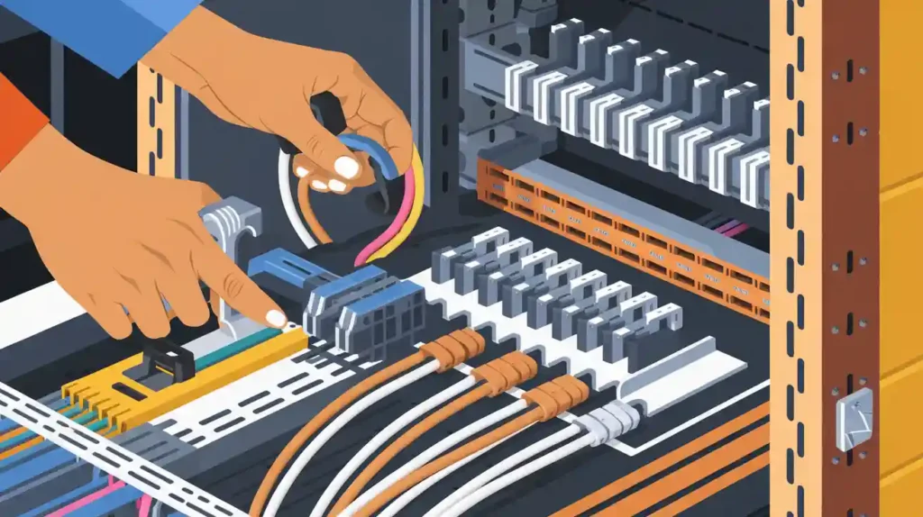
Physical Solutions
Physical solutions remain essential for organizing and protecting fiber optic cables in the field. You use cable trays, raceways, patch panels, and termination boxes to keep cables secure and accessible. These tools help you maintain order in data centers, telecom rooms, and outdoor installations.
Physical management solutions focus on structured cabling. You can easily label, route, and separate cables to prevent tangling and signal loss. For smaller or less complex environments, physical solutions provide a simple and effective way to manage fiber optic technology.
However, as your fiber optic infrastructure expands, you may find that physical solutions alone cannot keep up with the demands of large-scale, high-speed data transfer. Physical tools do not offer advanced analytics or real-time asset tracking. They also lack integration with other systems, such as GIS or ERP platforms.
Comparing Digital and Physical Solutions
You need to understand how digital and physical solutions compare when managing fiber optic networks:
|
Feature |
Digital Solutions (e.g., IQGeo FNMS) |
Physical Solutions (e.g., Patch Panels) |
|---|---|---|
|
Asset Tracking |
Real-time, automated |
Manual, periodic |
|
Data Visualization |
Geospatial maps, analytics |
Physical labels, diagrams |
|
Scalability |
High (cloud-based, multi-site) |
Limited (site-specific) |
|
Collaboration |
Multi-user, remote access |
On-site only |
|
Integration |
GIS, ERP, CRM, other digital systems |
Minimal |
|
Maintenance |
Automated alerts, predictive analytics |
Manual inspections |
|
Suitability |
Large, complex, high-speed networks |
Small, less complex environments |
You gain the most value when you combine both types of fiber optic solutions. Digital platforms like IQGeo’s FNMS give you centralized control and advanced analytics, while physical tools ensure your cables stay protected and organized on-site. This hybrid approach supports reliable digital data transmission and helps you deliver high-speed internet to your customers.
Note: For large-scale telecommunications projects, software-based fiber optic solutions improve efficiency and scalability. Physical solutions work best for smaller setups or as a complement to digital management.
By using both digital and physical solutions, you can build a robust fiber optic infrastructure that supports high-speed networking, reliable data transfer, and the future growth of your fiber optic networks.
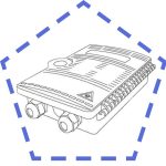
Termination Boxes
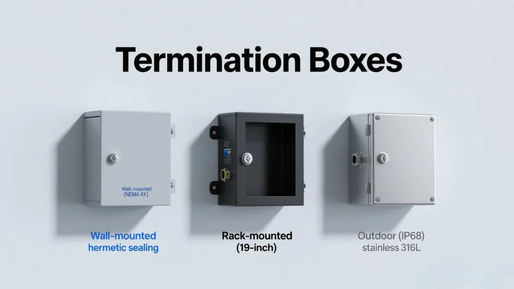
Fiber optic termination boxes play a key role in organizing, protecting, and managing fiber cable connections. You use these enclosures to secure fiber splices, connectors, and slack storage, which helps maintain signal integrity and simplifies maintenance. Choosing the right type of termination box depends on your installation environment and network requirements.
Wall-Mount
Wall-mount termination boxes offer a compact solution for managing fiber optic cables in areas with limited space. You can install these boxes almost anywhere on a wall, making them ideal for small offices, residential buildings, and network closets. Wall-mount boxes save valuable floor space and provide effective protection for your fiber connections.
Advantages of Wall-Mount Termination Boxes:
-
Save indoor space effectively
-
Easy to install and maintain
-
Protect fiber optic cables from physical damage
-
Flexible for use in residential, commercial, and data center networks
-
Allow some scalability for future expansion
|
Advantages |
Disadvantages |
|---|---|
|
Flexible installation location |
Limited scalability compared to rack-mounted boxes |
|
Space-saving, ideal for small areas |
Difficult access due to mounting height or position |
|
Easy installation without rack infrastructure |
Possible space constraints for future expansion |
|
Protects cables effectively |
Maintenance can be slower due to awkward access |
|
Suitable for environments lacking floor space |
Wall-mount boxes usually cost less than rack-mounted options. You benefit from lower installation expenses. However, you may find maintenance more challenging, especially if you need to reach boxes mounted high on a wall. Always follow TIA/EIA-568 standards for fiber termination and labeling to ensure compliance and easy troubleshooting.
Tip: For small-scale deployments or locations with limited floor space, wall-mount boxes provide a practical and affordable solution.
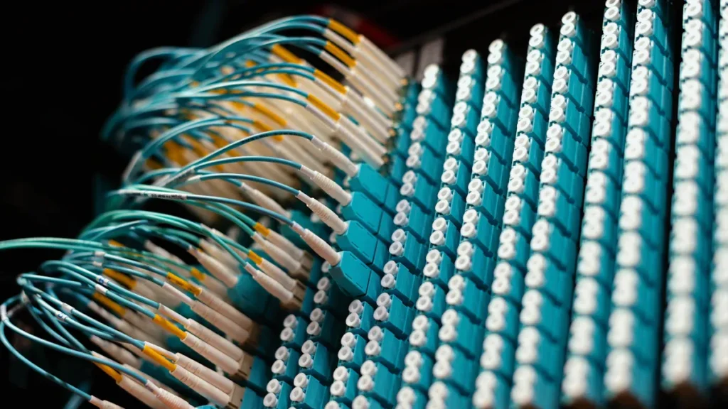
Rack-Mount
Rack-mount termination boxes are designed for high-density fiber management in 19-inch racks or enclosures. You often see these boxes in telecom rooms, enterprise networks, and large data centers. Rack-mount boxes help you organize and protect large numbers of fiber connections, which is critical for reliable network performance.
Typical use cases for rack-mount termination boxes:
-
Telecom rooms and central offices
-
Enterprise networks with high port density
-
Data centers requiring scalable cable management
-
Large IT infrastructures needing secure fiber termination
Rack-mount boxes simplify cable management and make it easier to scale your network as demand grows. You can access internal components quickly, which speeds up maintenance and troubleshooting. These boxes also help you maintain compliance with industry standards and best practices.
Note: Always reserve extra cable length (at least 1 meter) inside the rack for future repairs or re-termination, as recommended by TIA/EIA-568.
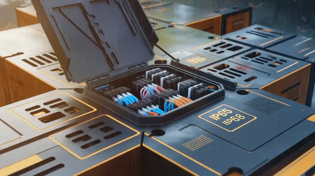
Outdoor
Outdoor termination boxes protect fiber optic cables from harsh environmental conditions. You need these boxes when installing fiber outside buildings, on utility poles, or underground. Outdoor boxes use durable materials like high-grade plastic or metal to resist moisture, dust, and temperature changes.
When selecting an outdoor termination box, consider the following factors:
-
Protection against moisture and dust (weatherproof gaskets and seals)
-
Resistance to temperature fluctuations
-
Durability against physical impacts, bumps, and vibrations
-
Secure locking mechanisms to prevent unauthorized access
Outdoor boxes must withstand a wide range of temperatures and physical disturbances to maintain fiber integrity. Always choose boxes rated for outdoor use and follow local codes for installation. Proper outdoor termination ensures your fiber network remains reliable, even in challenging environments.
Risk Alert: Inadequate outdoor protection can lead to water ingress, corrosion, and signal loss. Always verify the IP (Ingress Protection) rating before installation.
Cable Management Tools
Essential tools include fiber organizers, strain relief boots, and specialized testers—OTDRs and IL/RL meters validate installations while labeling systems and asset tracking software ensure long-term organization and maintenance efficiency.
Cable Managers
You need cable managers to keep your fiber optic cable organized and protected. Cable managers help you guide, support, and separate fiber cables inside racks, cabinets, or along walls. You can choose from horizontal and vertical cable managers. Horizontal cable managers fit between rack units and guide cables from side to side. Vertical cable managers run along the sides of racks and help you route cables up and down.
Cable managers often include features like D-rings, finger ducts, and covers. These features prevent sharp bends and reduce stress on fiber. You should use cable managers to keep fiber patch cords neat and easy to trace. This practice improves airflow and reduces the risk of accidental disconnections.
Tip: Always select cable managers that match the size and density of your fiber optic cable installation. This ensures you have enough space for future growth.
Ties and Straps
Ties and straps are essential for bundling and securing fiber optic cables. You can use hook and loop cable ties, which are gentle on fiber and easy to adjust. Avoid using plastic zip ties for fiber, as they can pinch and damage the cable. Instead, choose soft, reusable ties for better protection.
You may also need cable cleats, clamps, and hangers to support cables along trays or walls. These accessories keep fiber in place and prevent sagging. Electrical tapes and abrasion protection products, such as heat shrink tubing and grommet edging, add extra safety. They shield fiber from sharp edges and physical damage.
Here is a quick list of common accessories for fiber optic cable management:
-
Hook and loop cable ties
-
Cable cleats and clamps
-
Cable hangers and wire saddles
-
Heat shrink tubing and grommet edging
-
Electrical tapes
You should check all ties and straps regularly. Replace any that show signs of wear to maintain safe and reliable fiber cabling.
Trays and Raceway
Trays and raceway systems provide structured paths for fiber optic cables. You use wire mesh cable trays to support large bundles of fiber across long distances. These trays allow you to route cables above ceilings or below floors. Surface raceway systems offer enclosed channels that protect fiber from dust and impact.
Fiber routing systems include channels, bends, tees, and couplers. These parts help you direct fiber around corners and obstacles without exceeding the minimum bend radius. You can use mounting brackets and spillouts to secure cables at entry and exit points.
|
Tray/Raceway Type |
Best Use Case |
Key Features |
|---|---|---|
|
Wire mesh cable tray |
Data centers, long runs |
Open design, easy access |
|
Surface raceway |
Offices, exposed wall installations |
Enclosed, protects from dust/impact |
|
Fiber routing system |
Complex paths, tight spaces |
Modular, supports bends and branches |
You should always follow TIA/EIA-568 standards when installing trays and raceways. This ensures your fiber optic cable stays safe and performs well. Proper tray and raceway use also makes patch cord management easier, especially in high-density environments with many fiber patch cords.
Note: Good cable management with trays and raceways reduces the risk of signal loss and makes future upgrades simpler.
Patch Cord Management
Proper patch cord management is essential for maintaining the performance and reliability of your fiber optic cable infrastructure. You often face challenges such as tangled cables, excessive slack, and improper routing, which can lead to network downtime and increased maintenance costs. By following industry standards and best practices, you can keep your fiber patch cords organized and your cabling system efficient.
The table below summarizes the best practice for patch cord management in structured cabling environments:
|
Aspect |
Best Practice / Guidance |
Supporting Details |
|---|---|---|
|
Excessive Slack Control |
Limit slack using the “three-finger” guideline (no more than 5 inches of slack) |
Excess slack causes manageability and bend radius issues; 93% of cords in studies had too much slack |
|
Patch Cord Routing |
Use horizontal and vertical patch-cord management systems |
Horizontal managers (rings, clips, channels) protect bend radius; vertical systems can overfill |
|
Bend Radius Management |
Maintain minimum bend radius (4x cable diameter for fiber optic cable) |
Kinking and signal loss occur if bend radius is not maintained, especially in vertical managers |
|
Supplemental Supports |
Use hook-and-loop or cable ties only as supplemental aids |
Velcro and tie wraps help tidiness but do not replace proper management hardware |
|
Patch Cord Quality |
Choose manufactured patch cords for reliability |
Manufactured cords provide consistent quality; handmade cords often have slack and fit issues |
|
Standards Guidance |
Follow TIA/EIA-568A and ISO/IEC-11801 for routing and dressing |
Standards ensure effective organization and long-term reliability |
You should always control slack in your fiber patch cords. Excess slack not only looks messy but also increases the risk of exceeding the minimum bend radius. This can cause microbends or kinks in the fiber, leading to signal loss or even permanent damage. Use the “three-finger” rule to keep slack under control. If you see more than 5 inches of slack, you need to adjust your cables.
When routing patch cords, select horizontal cable management hardware like distribution rings or routing channels. These tools help you maintain the correct bend radius and prevent tangling. Vertical managers can be useful, but you must avoid overfilling them. Too many cables in one space can lead to entanglement and make it hard to trace individual fiber optic cable runs.
Always use hook-and-loop ties or Velcro straps as supplemental supports. Avoid using plastic zip ties as the main method for securing fiber. Tight ties can pinch the fiber and cause signal degradation. Instead, use them to group cables loosely and keep your cabling neat.
Choose high-quality, manufactured patch cords whenever possible. These cords offer better reliability and consistent performance compared to handmade options. Manufactured cords also help you maintain proper lengths, reducing slack and improving overall cable management.
Tip: Follow TIA/EIA-568A and ISO/IEC-11801 standards for patch cord management. These standards provide clear guidelines for routing, dressing, and securing fiber optic cable in structured cabling systems.
Frequent moves and changes are common in active network environments. You should regularly inspect your fiber patch cords for signs of kinking, excessive slack, or improper routing. Quick corrections help you prevent network issues before they escalate.
By applying these best practices, you can ensure your fiber optic cable installation remains organized, efficient, and ready for future growth.
Structured Cabling
Structured cabling forms the backbone of modern networking. You rely on it to support reliable data transfer and future network growth. By following best practices in design, routing, and segregation, you can build a fiber infrastructure that meets both current and future needs.
Design
When you design a structured cabling system for fiber, you must consider several key factors to ensure performance and longevity:
-
Plan for both current and future network needs. This ensures your structured cabling supports growth and new technologies.
-
Map cable routing to avoid electromagnetic interference and allow easy access for changes.
-
Follow industry standards like TIA/EIA-568 for all components and installation steps.
-
Choose high-quality cables, connectors, racks, and enclosures from trusted manufacturers.
-
Use professional design and installation services to guarantee reliability.
-
Select the right cable types. Fiber optics work best for long-distance and high-speed data transfer.
-
Implement proper cable management with trays, patch panels, and clear labeling.
-
Keep cable lengths within recommended limits. Use fiber for longer runs to prevent signal loss.
-
Test all cables after installation with certification tools to verify performance.
-
Document every cable route, termination, and specification for easy maintenance and upgrades.
Structured cabling design also requires you to consider cable distances. Fiber allows longer runs than copper. You should perform a loss budget analysis to confirm the fiber link supports your network electronics. Choose OM3 or OM4 multimode fiber for high-speed, moderate distances. Use singlemode fiber for long backbone links. Always control environmental factors like temperature and moisture to prevent cable degradation. Work with facility owners and engineers to plan pathways and spaces for your cabling.
Tip: Good documentation and planning make future upgrades and troubleshooting much easier.
Routing
Proper routing protects your fiber and maintains optimal data performance. You should always avoid sharp bends that exceed the minimum bend radius. This protects the glass fibers inside the cable from damage. Make sure you do not exceed the cable’s tensile strength during installation. Use cable trays and raceways to guide and support your structured cabling. Avoid improper bundling, which can lead to tangling and signal loss. Shield your fiber from electromagnetic interference by keeping it away from power cables and sources of electrical noise.
|
Routing Practice |
Benefit |
|---|---|
|
Maintain bend radius |
Prevents fiber breakage and signal loss |
|
Use cable trays |
Supports and organizes cabling |
|
Avoid over-tight bundling |
Reduces risk of physical damage |
|
Separate from power |
Minimizes interference |
Regular inspections help you catch routing issues early. This keeps your structured cabling system reliable and efficient.
Segregation
Segregation is a key part of structured cabling. You must separate fiber from copper cables and power lines. This reduces the risk of interference and physical damage. Use dedicated pathways and enclosures for each cable type. Label all cables clearly to avoid confusion during maintenance. Segregation also helps you comply with safety standards and makes troubleshooting faster.
Note: Segregating fiber from other cabling types protects your data and extends the life of your network infrastructure.
By focusing on design, routing, and segregation, you ensure your structured cabling supports high-speed networking and reliable data transfer. These network cabling essentials help you build a system that is organized, scalable, and ready for the future.
Labeling Standards
Proper labeling is essential for managing fiber optic cables in any network. You need clear, consistent labels to identify cables, connectors, and routes. This practice reduces errors, speeds up troubleshooting, and supports future upgrades. Following industry standards ensures your labeling system works for everyone on your team.
Labeling Fiber Optic Cables
You should follow the latest TIA-568.3-E standard when labeling fiber optic cables. This standard helps you distinguish between different cable types and connector styles, especially as networks become more complex.
-
Green now marks both multimode and singlemode APC (Angled Physical Contact) MPO connectors. Because of this, cable color becomes the main way to tell multimode from singlemode cables.
-
Changes in fiber polarity and transitions, such as Type-U1 and Type-U2, affect how you label and identify cables. Type-U2 transitions flip fiber pairs, which supports direct breakout connections and impacts your labeling strategy.
-
Trunk cables are pinned, while MPO-to-LC cassettes, modules, fan-out cables, and MPO patch cords are unpinned. This supports end-to-end MPO duplex applications and migration to MPO-based equipment ports.
Tip: Always update your labeling system when you change polarity methods or cable types. This keeps your documentation accurate and prevents confusion.
Color Coding
Color coding makes it easy for you to identify fiber types and connectors at a glance. The TIA-598 standard defines how you should use colors for jackets, inner fibers, and connectors.
-
Cable Jacket Colors: Outer jackets use specific colors to show fiber type. For example, yellow means singlemode, orange means OM1/OM2 multimode, aqua means OM3, and magenta means OM4. If a cable has multiple fiber types, printed legends show the fiber count and types.
-
Inner Fiber Colors: Inside the cable, each fiber uses a distinct color. For up to 12 fibers, you see 12 unique colors. If your cable has more than 12 fibers, the color sequence repeats with extra markings to show different groups.
-
Connector Colors: Connector colors also help you. Beige or black means OM1/OM2 multimode, aqua means OM3, magenta means OM4, blue means singlemode UPC (Ultra Physical Contact), and green means APC.
|
Fiber Type |
Jacket Color |
Connector Color |
|---|---|---|
|
Singlemode |
Yellow |
Blue (UPC), Green (APC) |
|
OM1/OM2 Multimode |
Orange |
Beige/Black |
|
OM3 Multimode |
Aqua |
Aqua |
|
OM4 Multimode |
Magenta |
Magenta |
Note: Using the correct color codes helps you avoid costly mistakes and makes network changes much faster.
Documentation
Accurate documentation supports your entire cable management process. You need to keep detailed records from installation through maintenance.
-
Record every cable route, connection point, and test result. This gives you a clear map of your network.
-
Label every cable and connector. Proper labels help you find and fix problems quickly.
-
Organize cables with color-coded labels or markers. This makes management and troubleshooting easier.
Risk Alert: Poor documentation can lead to lost cables, increased downtime, and higher maintenance costs. Always keep your records up to date.
By following these labeling standards, you ensure your fiber optic network stays organized, efficient, and ready for future growth.
Indoor & Outdoor Install
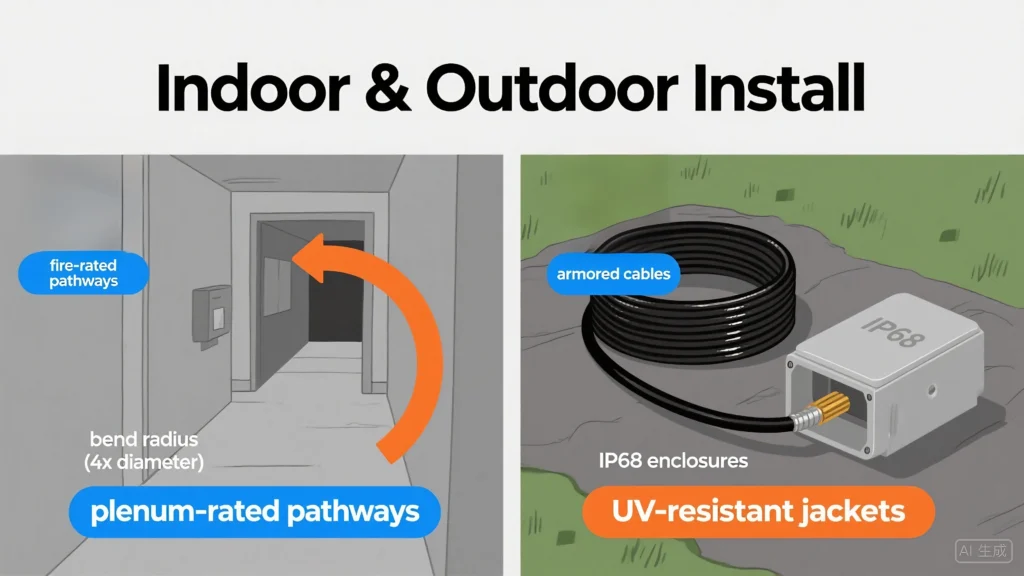
Indoor installations demand fire-rated pathways and bend radius control in confined spaces, while outdoor deployments require armored cables, hydrophobic gels, and specialized grounding—both demanding rigorous maintenance protocols preserving signal integrity.
Indoor Routing
When you plan fiber optic installation inside a building, you need to focus on safety, flexibility, and compliance. Indoor fiber optic cables come in several types, such as simplex, duplex, distribution, and breakout. These cables are designed for short distances and dry environments. You often install them in raceways, cable trays, or conduits. Their compact and flexible structure lets you route them through tight spaces, ceilings, and walls.
You must always follow fire safety standards. Many indoor cables are plenum-rated, which means they limit toxic smoke if a fire occurs. This is important for protecting people and equipment. You should also avoid electromagnetic interference by keeping fiber away from power lines and heavy machinery. Use protective conduits to shield cables from accidental damage.
Tip: Before starting any indoor fiber optic installation, review the building’s layout and plan your cable routes to minimize sharp bends and long runs.
Outdoor Protection
Outdoor fiber optic cable installation faces different challenges. You need cables that can handle harsh weather, moisture, and physical stress. Outdoor cables often use loose tube or aerial/self-supporting designs. These cables have water-blocking gels or tapes to keep moisture out. They also have strong jackets and reinforcements for extra durability.
Key features of outdoor fiber optic cables include:
-
UV-resistant coatings to protect against sunlight
-
Water-blocking materials for underground or wet areas
-
Reinforced strength members for aerial installations
-
Weatherproof enclosures for connectors
You must inspect outdoor cables regularly for signs of UV damage, animal interference, or physical wear. Always use weatherproof fiber boxes and seal all entry points to prevent water ingress. When you bury cables, make sure they are deep enough to avoid accidental cuts from digging.
Note: Outdoor fiber optic installation requires careful planning to protect cables from temperature changes, moisture, and mechanical stress.
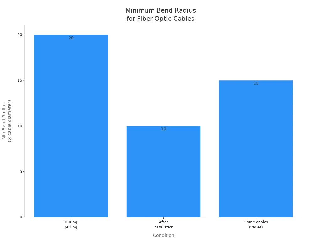
Bend Radius
Bend radius is a critical factor in every fiber optic cable installation. The bend radius is the smallest curve you can make with a fiber without causing signal loss or damage. If you bend the cable too tightly, you risk breaking the fiber or increasing signal attenuation.
The minimum bend radius depends on the cable type and installation condition. For example, single-mode fibers usually need a larger bend radius than multimode fibers. You should always check the manufacturer’s specifications, but here are general guidelines:
|
Condition |
Minimum Bend Radius (times cable diameter) |
|---|---|
|
During pulling (under tension) |
20 |
|
After installation (no tension) |
10 |
|
Some cables (varies by type) |
15 |
If you have a cable with a 13mm diameter, you should not bend it below a 260mm radius during pulling. Exceeding the minimum bend radius can cause permanent damage and degrade network performance.
Risk Alert: Always maintain the correct bend radius during all cabling installations. Ignoring this rule can lead to costly repairs and downtime.
Crush Protection
Crush protection is a critical part of every fiber optic installation. You need to protect each fiber optic cable from physical pressure that can cause microbends, cracks, or even complete breaks. When you install fiber, you often route cables through crowded spaces, under floors, or inside conduits. Heavy equipment, foot traffic, or even tight cable bundles can put dangerous pressure on the cable jacket (the outer protective layer).
Risk Alert: Even a small amount of crushing force can increase signal loss by more than 3 dB, according to Corning research. This level of loss can disrupt your entire network.
Why Crush Protection Matters
Fiber optic cable contains delicate glass strands. These strands transmit light signals with very little loss. If you crush the cable, you risk damaging the core (the light-carrying part) or the cladding (the layer that keeps light inside the core). Damaged fiber leads to higher attenuation (signal loss), unreliable connections, and expensive repairs.
Common Sources of Crushing
You should watch for these common sources of crushing during installation:
-
Heavy objects placed on top of cable trays or raceways
-
Overfilled conduits or ducts
-
Tight cable ties or straps that pinch the cable
-
Cables caught in doorways or under equipment
-
Improper stacking of reels during storage
Best Practices for Crush Protection
You can prevent crushing damage by following these best practices:
-
Use Armored Fiber Optic Cable: Choose cables with built-in armor (metallic or non-metallic) for areas with high risk of impact or pressure.
-
Install Cable Trays and Conduits: Support cables with trays, raceways, or conduits that meet TIA/EIA-568 and ISO/IEC 14763 standards. These structures distribute weight and prevent direct pressure.
-
Avoid Overfilling: Never exceed the fill capacity of trays or conduits. Overfilling increases pressure on each fiber.
-
Select Proper Cable Ties: Use wide, soft hook-and-loop ties. Avoid plastic zip ties, which can pinch and crush the cable.
-
Label and Route Carefully: Mark all pathways and avoid routing cables through high-traffic areas.
-
Inspect After Installation: Check all fiber optic cable runs for signs of pinching or flattening. Replace any damaged sections immediately.
|
Protection Method |
Application Area |
Benefit |
|---|---|---|
|
Armored cable |
Outdoor/industrial zones |
High crush resistance |
|
Cable tray/raceway |
Data centers, offices |
Even weight distribution |
|
Hook-and-loop ties |
Racks, patch panels |
Gentle support, no pinching |
|
Warning labels |
All pathways |
Prevents accidental crushing |
Tip: Always follow manufacturer guidelines for minimum crush resistance. For example, many fiber optic cable designs specify a maximum crush load of 220 N/100 mm.
You should train your team to recognize and avoid crush hazards during every fiber optic installation. Regular inspections and proper documentation help you catch problems early and keep your network running smoothly.
Testing & Repair
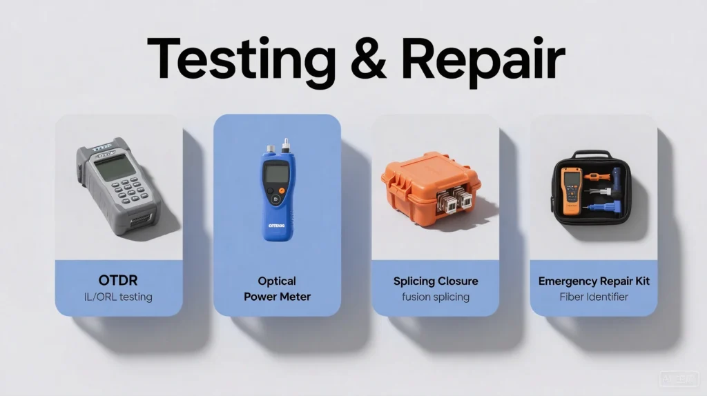
Proactive testing via OTDR traces and BERT validation identifies degradation early, while structured repair protocols—including splice verification and contamination removal—minimize downtime through systematic fault isolation and restoration.
Testing Standards
You need to test every fiber optic cable to make sure your network works reliably. Testing standards help you check the quality and performance of your fiber optic installation. These standards come from international organizations that set the rules for how you should test and measure fiber optic systems.
Key International Standardization Bodies:
-
International Electrotechnical Commission (IEC): Sets global standards for electrical and electronic technologies, including fiber optics.
-
Institute of Electrical and Electronics Engineers (IEEE): Publishes technical standards for fiber optic systems and components.
-
Telecommunications Industry Association (TIA): Develops standards for information and communications technology, such as TIA/EIA-568 for structured cabling.
You should follow these standards to ensure your fiber optic network meets industry requirements. They help you avoid problems like signal loss, poor connections, and safety risks.
Common Fiber Optic Testing Methods
|
Test Type |
What It Measures |
Why It Matters |
|---|---|---|
|
Insertion Loss (IL) |
Signal loss as light passes through a fiber link |
Checks for excessive loss at connectors |
|
Optical Return Loss (ORL) |
Amount of light reflected back at connection points |
Identifies poor splices or dirty ends |
|
OTDR Testing |
Fiber length, faults, and loss along the cable |
Locates breaks, bends, or weak spots |
-
Insertion Loss (IL) Testing: Measures how much signal you lose as light travels through connectors, splices, and cables. High insertion loss means you may have dirty connectors or poor splices.
-
Optical Return Loss (ORL) Testing: Checks how much light reflects back toward the source. Too much reflection can damage equipment or cause data errors.
-
Optical Time Domain Reflectometer (OTDR) Testing: Sends light pulses down the fiber and measures reflections. This test helps you find faults, measure cable length, and check for bends or breaks.
Tip: Always test new fiber optic installations before you connect them to your network. This step helps you catch problems early and avoid costly repairs.
Why Testing Standards Matter
You need to follow these standards for several reasons:
-
They ensure your fiber optic system delivers the speed and reliability you expect.
-
They protect technicians and users by including safety measures.
-
They help you meet legal and regulatory requirements for communication infrastructure.
UL Solutions and similar organizations offer testing and certification services. These services help you prove your cables meet international standards. Certification reduces supply chain risks and protects your company’s reputation. You can trust that your fiber optic cables will perform well in North America, Europe, Asia, and other regions.
Risk Alert: Skipping proper testing can lead to hidden faults, network downtime, and expensive troubleshooting. Always use certified testing equipment and follow the latest standards from IEC, IEEE, and TIA.
By following recognized testing standards, you keep your fiber optic network safe, reliable, and ready for future growth.
Splice Closure
Fiber Splice closures are essential enclosures designed to protect fiber optic splices from environmental damage while maintaining signal integrity. These rugged containers house the critical fusion or mechanical splices that join fiber optic cables, ensuring long-term reliability in both indoor and outdoor environments.
Types of Splice Closures
You can choose from several closure designs based on your installation requirements:
| Closure Type | Application | Key Features |
|---|---|---|
| Dome-shaped | Aerial, underground | Weatherproof, UV resistant, easy access |
| Inline | Direct burial, duct installations | Compact design, low profile |
| Wall-mount | Indoor, telecom rooms | Space-saving, secure locking |
| Rack-mount | Data centers, equipment rooms | High density, integration with structured cabling |
Installation Best Practices
When installing splice closures, follow these guidelines to ensure optimal performance:
- Proper Sealing: Use heat-shrink boots and gasketed entry ports to prevent moisture ingress (IP68 rating minimum for outdoor use)
- Strain Relief: Secure cables with built-in clamps to prevent tension on splices
- Splice Organization: Use splice trays with numbered positions for easy identification
- Slack Storage: Leave 1-1.5 meters of excess fiber for future repairs or reconfiguration
- Environmental Protection: Select closures rated for the specific temperature range and exposure conditions
Tip: Always perform a pull test after installation to verify cable security without stressing the splices.
Maintenance Considerations
Regular inspection of splice closures helps prevent unexpected failures:
- Schedule quarterly visual inspections for outdoor closures
- Check for signs of water intrusion, corrosion, or pest damage
- Verify that all entry ports remain properly sealed
- Document splice locations and test results for troubleshooting
- Replace aging closures before they reach end-of-life (typically 10-15 years)
Emergency Repair
Emergency fiber optic repairs require rapid response to minimize network downtime. Having a well-documented emergency protocol and properly stocked repair kit can significantly reduce restoration time.
Emergency Repair Procedures
Follow this structured approach when responding to fiber optic failures:
- Identify the Fault: Use OTDR and visual fault locators to pinpoint the exact location and nature of the break
- Assess the Damage: Determine if a temporary repair or full replacement is needed
- Isolate the Affected Segment: Use patch panels or bypass switches to reroute traffic if possible
- Deploy Emergency Splicing: For critical links, perform fusion splicing immediately; use mechanical splices for temporary fixes
- Test and Verify: Conduct insertion loss and OTDR tests to ensure repair quality
- Document and Report: Record repair details, test results, and follow-up actions needed
Essential Emergency Tools
Your emergency repair kit should include:
- Portable fusion splicer with backup batteries
- Fiber strippers, cleavers, and cleaning supplies
- Mechanical splice kits (minimum 12 per kit)
- Heat-shrink sleeves and portable heater
- OTDR or fiber fault locator
- Emergency power supply
- Weatherproof temporary enclosures
- Spare cable (minimum 50 meters) and connectors
Risk Alert: Using improper emergency repair techniques can lead to higher signal loss and potential network instability. Always follow manufacturer guidelines for temporary splices.
Preventive Measures
Minimize emergency repair needs with these proactive strategies:
- Implement 24/7 network monitoring with automatic fault detection
- Conduct regular OTDR testing of critical links
- Maintain proper cable slack for easier repairs
- Protect aerial cables with bird guards and impact sleeves
- Install redundant paths for mission-critical connections
- Train technicians in rapid response procedures
- Document all cable routes with GPS coordinates
By combining proper emergency preparedness with preventive maintenance, you can reduce both the frequency and impact of fiber optic network failures.
Fiber Identifier
Fiber identifiers are essential tools for anyone who manages or troubleshoots fiber optic networks. You use these devices to quickly locate faults, verify connections, and measure signal quality. By choosing the right fiber identifier, you can reduce downtime, improve network reliability, and make maintenance much easier.
You often face challenges when trying to find the exact location of a break or high-loss event in a fiber optic cable. Fiber identifiers help you pinpoint these issues without guesswork. Each tool serves a specific purpose, from simple visual checks to advanced diagnostic analysis.
Here is a comparison of the most commonly used fiber identifiers and how they assist you in network troubleshooting:
|
Fiber Identifier |
Function in Network Troubleshooting |
How It Assists Troubleshooting |
|---|---|---|
|
Visual Fault Locator (VFL) |
Emits visible laser light to locate breaks or faults in fiber optic cables |
Quickly identifies visible breaks or faults by light leakage, saving time locating faults and reducing downtime |
|
Optical Loss Test Set (OLTS) / Light Source and Power Meter (LSPM) |
Measures optical loss and verifies continuity and polarity |
Determines if loss is on a single fiber or all fibers, helping isolate damage to cable or connectors; verifies link meets requirements |
|
Optical Fault Finders (e.g., Fiber QuickMap) |
Sends laser pulses and measures reflected light to identify high loss events and breaks on multimode fibers up to ~1.5 km |
Quickly measures fiber length and locates high loss events and breaks; simple to use and effective for mid-range troubleshooting |
|
Optical Time Domain Reflectometer (OTDR) |
Sends laser pulses and measures backscatter to locate breaks, bends, splices, connectors, and quantify loss at events |
Provides detailed event location and loss measurement, offering comprehensive troubleshooting and quality assessment |
|
Passive Optical Network (PON) Power Meter (PPM) |
Measures optical power levels at multiple wavelengths in PONs and fiber networks |
Performs automated pass/fail tests, measures power at various points, crucial for maintaining and troubleshooting PONs |
How to Use Fiber Identifiers in Practice:
-
Visual Fault Locator (VFL):
You connect a VFL to the fiber. The device emits a bright red laser that leaks out at breaks or sharp bends. You can see the light with your eyes, which helps you find faults quickly. This tool works best for short distances and patch cords. -
Optical Loss Test Set (OLTS) / Light Source and Power Meter (LSPM):
You use this set to measure how much signal is lost as it travels through the fiber. It helps you check if the link meets TIA/EIA-568 standards. If you see high loss, you know there is a problem with the cable or connectors. -
Optical Fault Finders:
These devices send pulses of light and measure what comes back. You can use them to find breaks or high-loss points in multimode fibers up to about 1.5 kilometers. They are simple and fast for mid-range troubleshooting. -
Optical Time Domain Reflectometer (OTDR):
An OTDR gives you a detailed map of the fiber. It shows you where splices, connectors, bends, and faults are located. You can use it for advanced troubleshooting and to document the quality of your installation. -
Passive Optical Network (PON) Power Meter (PPM):
This meter checks the power levels at different wavelengths in PON systems. You can use it to perform automated pass/fail tests and ensure your network delivers the right signal strength.
Tip: Always select the right fiber identifier for your task. For quick checks, use a VFL. For detailed analysis, choose an OTDR. Regular use of these tools helps you maintain a reliable and high-performance fiber optic network.
By understanding and using fiber identifiers, you can troubleshoot problems faster, reduce downtime, and keep your network running smoothly.
Accessories
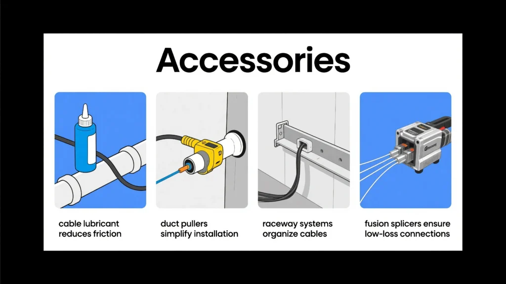
Essential accessories—strain relief boots, splice organizers, and color-coded labels—protect connections while IL/RL meters and cleaning tools maintain signal integrity, ensuring physical and optical reliability throughout the cable lifecycle.
Cable Lubricant
You need cable lubricant when pulling fiber optic cables through conduits or ducts. Cable-pulling lubricants lower the friction between the cable jacket and the conduit wall. This reduction in friction helps you pull cables over long distances and through multiple bends without exceeding the cable’s maximum tension rating. Lower pulling tension means you reduce the risk of damaging the fiber during installation.
When you select a lubricant, always check that it is compatible with your cable jacket material. Using the wrong lubricant can cause the jacket to swell or crack, leading to costly repairs. The right lubricant can reduce the coefficient of friction to 0.1 or even lower, making the process much smoother. You also want a lubricant that is easy to apply and clean up after the job.
Benefits of using cable lubricant:
-
Allows longer uninterrupted cable runs
-
Minimizes sidewall pressure in bends
-
Decreases equipment wear and improves safety
-
Keeps pulling forces within manufacturer-specified limits
Tip: Always follow the cable manufacturer’s recommendations for lubricant type and application method. This ensures you protect your fiber and meet industry standards.
Duct Pulling
Duct pulling is a critical step in fiber optic cable installation. You must use proper techniques to avoid damaging the delicate glass fibers inside the cable. Start by testing the cable before pulling to check for any pre-existing damage. Set up the cable spool so the cable pays off from the top. This prevents twisting and stress on the fiber.
Follow these steps for safe duct pulling:
-
Test the cable before pulling.
-
Pay off the cable from the top of the spool.
-
Reel the cable off without spinning it over the edge.
-
Always pull using the cable’s strength member, not the fiber itself.
-
Avoid pulling on the outer jacket to prevent elongation and compression.
-
Maintain a uniform pulling force below the cable’s specified limit (often 600 lbs for outside-plant cables).
-
Do not jerk the cable; keep the force steady.
-
Maintain a bend radius of at least 20 times the cable diameter during pulling.
-
Use tension-monitoring equipment or breakaway swivels with power equipment.
-
Use innerducts to protect the cable from sharp edges or protrusions.
|
Step |
Why It Matters |
|---|---|
|
Test cable |
Detects pre-existing faults |
|
Use strength member |
Prevents fiber breakage |
|
Maintain bend radius |
Avoids microbends and signal loss |
|
Monitor tension |
Keeps force within safe limits |
Note: Industry standards like TIA/EIA-568 and ISO/IEC 14763 require you to monitor pulling tension and bend radius to prevent fiber damage.
Raceway Install
Raceway systems help you organize and protect fiber optic cables during installation. You use raceways to route cables along walls, ceilings, or under floors. These systems shield cables from physical damage and keep them separated from power lines, reducing the risk of interference.
When you install a raceway, plan your cable paths in advance. Choose a raceway size that allows for future expansion. Avoid sharp bends and overfilling, as these can increase the risk of signal loss or cable damage. Use mounting brackets and secure covers to keep cables in place and prevent accidental contact.
Checklist for raceway installation:
-
Select the right size and type of raceway for your cable count
-
Plan routes to minimize bends and avoid obstacles
-
Use proper mounting hardware for secure attachment
-
Label all pathways for easy identification and maintenance
-
Leave space for future cable additions
Risk Alert: Overfilled or poorly installed raceways can lead to crushed cables and increased attenuation. Always follow TIA/EIA-568 guidelines for raceway fill capacity and bend radius.
By using the right accessories and following best practices, you ensure your fiber optic installation is safe, efficient, and ready for future upgrades.
Fusion Splicer
A fusion splicer is a key tool for joining two fiber optic cables with minimal signal loss. You use this device to align and fuse the glass cores (the light-carrying part of the fiber) using an electric arc. This process creates a nearly seamless connection, which is critical for high-speed data transmission and long-distance links.
Why You Need a Fusion Splicer
You need a fusion splicer when you want to:
-
Repair broken fiber optic cables in the field.
-
Connect new fiber runs during network expansion.
-
Minimize insertion loss (signal loss at the splice point).
-
Ensure long-term reliability for mission-critical networks.
Fusion splicing offers lower attenuation (signal loss) and higher strength compared to mechanical splicing. According to TIA/EIA-568 and ISO/IEC 14763 standards, fusion splicing is the preferred method for permanent fiber connections.
How to Use a Fusion Splicer
You can follow these steps to achieve a high-quality splice:
-
Prepare the Fiber: Strip the protective coating from the fiber using a fiber stripper. Clean the bare glass with lint-free wipes and isopropyl alcohol.
-
Cleave the Fiber: Use a precision cleaver to create a flat, perpendicular end face. A good cleave is essential for a low-loss splice.
-
Place Fibers in the Splicer: Insert both fibers into the fusion splicer’s holders. The machine automatically aligns the cores using cameras and motors.
-
Fuse the Fibers: Start the fusion process. The splicer generates an electric arc that melts and joins the glass ends.
-
Protect the Splice: Slide a heat-shrink sleeve over the splice and use the splicer’s heater to secure it. This protects the joint from moisture and mechanical stress.
-
Test the Splice: Use an Optical Time Domain Reflectometer (OTDR) to verify splice quality. Check that the loss is within acceptable limits (typically <0.1 dB per splice).
Tip: Always follow the manufacturer’s instructions and TIA/EIA-568 guidelines for best results.
Fusion Splicing vs. Mechanical Splicing
|
Feature |
Fusion Splicing |
Mechanical Splicing |
|---|---|---|
|
Typical Loss |
0.01–0.1 dB |
0.2–0.75 dB |
|
Strength |
High |
Moderate |
|
Cost per Splice |
Higher initial, lower ongoing |
Lower initial, higher ongoing |
|
Use Case |
Permanent, high-performance |
Temporary, quick repair |
You should choose fusion splicing for permanent installations and high-bandwidth networks. Mechanical splicing works for temporary fixes or emergency repairs.
Risks and Best Practices
Risk Alert: Poor fiber preparation or dirty tools can increase splice loss by over 300%. Always clean and inspect fibers before splicing.
-
Store your fusion splicer in a dust-free case.
-
Calibrate the splicer regularly.
-
Replace cleaver blades as needed.
-
Document each splice location and test result for future maintenance.
By mastering the use of a fusion splicer, you ensure your fiber optic network remains fast, reliable, and ready for future demands.
You achieve effective fiber optic cable management by following industry standards, labeling cables, and protecting against physical damage. Combining digital tools like IQGeo’s FNMS with physical solutions lets you monitor your data infrastructure in real time, automate tasks, and reduce operational costs. This hybrid approach bridges gaps between IT and facilities, supports early detection of issues, and optimizes data flow. Regular testing and ongoing maintenance keep your network reliable. Advanced management systems help you future-proof your data infrastructure for growth.


 Fiber Optic Termination Boxes
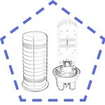 Fiber Optic Splice Enclosures
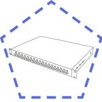 Fiber Patch Panels
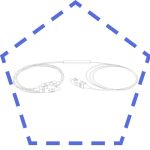 PLC Splitters
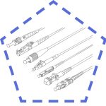 Fiber Optic Pigtails
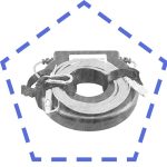 OTDR Launch Cables
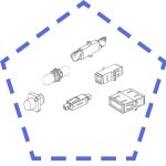 Fiber Optic Adapters
 Fiber Optic Patch Cords