
 Fiber Optic Termination Boxes
 Fiber Optic Splice Enclosures
 Fiber Patch Panels
 PLC Splitters
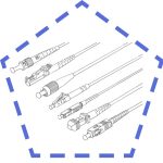 Fiber Optic Pigtails
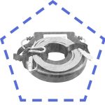 OTDR Launch Cables
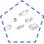 Fiber Optic Adapters
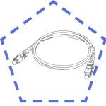 Fiber Optic Patch Cords
Tensile strength measures the maximum pulling force a fiber optic cable can withstand before breaking. You rely on this property to ensure the reliability of your cable during installation and operation. Proper tensile strength testing helps you prevent cable damage and maintain network performance. Factors like cable design, material choice, and environmental conditions all affect tensile strength and overall reliability. When you understand these elements, you improve the durability and reliability of your fiber optic cable system.
Key Takeaways
Tensile strength shows how much pulling force a fiber optic cable can handle before breaking, which is vital for cable durability and network reliability.
Cable design, materials, coatings, and environmental conditions all affect tensile strength and must be considered to improve cable performance.
Proper sample preparation and use of calibrated tensile testing machines ensure accurate measurement of cable strength and help prevent damage.
Following industry standards and documenting test results guarantee compliance, quality control, and legal protection.
Careful handling during installation, including respecting load limits and bend radius, plus using monitoring tools, protects cables from damage and maintains signal quality.
Tensile Strength Fundamentals
Tensile strength defines maximum safe pulling tension during installation, with testing protocols verifying cable resilience to axial forces—core pillar for aerial/dynamic installations preserving signal integrity through material science.
What Is Tensile Strength?
Tensile strength tells you how much pulling force a fiber optic cable can handle before it breaks. You measure this property during testing by applying tension to the cable until it snaps. The result shows the maximum load the cable can withstand without failing. In fiber optic cables, tensile strength is usually measured in pounds per square inch (psi) or Newtons per square meter (N/m²). This value helps you understand the cable’s mechanical durability and its ability to survive real-world installation and operation.
Standard fiber optic cables used in commercial installations are proof-tested to tensile strengths of either 50 kpsi or 100 kpsi. The 50-kpsi fiber has shown reliable performance for nearly 20 years without tensile strength-related failures. Most fibers actually exceed 300 kpsi for 99.9% of 1-km lengths, so the proof-test values are conservative minimums. Cable design and manufacturing quality often influence overall cable strength and longevity more than the nominal proof-test rating.
Key Influencing Factors
Several factors affect the tensile strength of fiber optic cables:
The design of the cable, including the size of the optical core and the thickness of the cladding, plays a big role.
Coating materials protect the optical fiber from mechanical stress and environmental hazards.
The manufacturing process, such as how you draw and coat the fiber, impacts the final strength.
The construction type, like tight-buffered or loose-tube, and the use of strength members or reinforcements, can increase tensile performance.
Environmental conditions, such as temperature changes, moisture, and UV exposure, may reduce tensile strength over time.
Importance for Fiber Optic Cable
Tensile strength is critical for the performance and reliability of fiber optic cables in telecommunications networks. You need to manage tension carefully to keep cables working well for years. If you apply too much tensile force, you risk cable elongation, signal attenuation, or even breaking the optical fibers. Proper tension management prevents mechanical damage and keeps your signal strong.
Tip: Always use engineering calculations, field testing, and ongoing monitoring to ensure your cables meet tensile strength requirements. These steps help prevent fiber deformation or fracture, which extends the lifespan of your fiber optic cable and maintains network reliability.
When you understand and test tensile strength, you protect your investment and ensure high-quality signal transmission.
Fiber Optic Cable Design and Materials
Reinforcement elements like aramid yarns and FRP rods define tensile resilience, while advanced polymer jackets combat environmental stress—material science innovations enabling higher load tolerance during critical installations.

Core and Cladding
You find the core and cladding at the heart of fiber optic cables. The core carries the optical signal, while the cladding surrounds it and keeps the light inside. Both parts use glass or plastic, but the core has a higher refractive index. This difference lets the optical signal travel long distances with little loss. The size and thickness of the core and cladding affect how much force the cable can handle. If you choose a larger core or thicker cladding, you often get better durability and strength. Material composition plays a big role in how the cable reacts to pulling forces. For example, cables with different sheaths or inner components can fail in different ways during tensile testing. The way the core and cladding interact with the outer sheath can also change the cable’s failure pattern.
Coatings and Strength Members
You protect the optical fiber with coatings and strength members. Coatings shield the fiber from scratches, moisture, and other hazards. They also help the cable resist bending and stretching. The choice of coating material affects the cable’s durability and mechanical performance. Strength members add extra support. You often see aramid yarns (Kevlar) in fiber optic cables because they are strong, light, and resist stretching. Fiberglass rods give the cable rigidity without adding much weight. Steel wire strands provide extra protection in tough environments. These materials work together to keep the cable safe during installation and use. When you select the right strength members, you improve the cable’s ability to handle tension and maintain performance.
Material properties like tensile strength, elasticity, and abrasion resistance shape how well the cable performs.
Design factors such as load, bending, and maintenance affect the cable’s lifespan and durability.
Steel wire ropes offer high strength but need protection from corrosion.
You can optimize cable design by choosing the right materials and construction.
Environmental Impact
Environmental testing helps you understand how fiber optic cables react to real-world conditions. Temperature and humidity can change the cable’s properties over time. For example, high temperatures can make the coating stiffer, while moisture can weaken the bond between the coating and the optical fiber. The table below shows how different parts of the cable respond to environmental exposure:
Property/Interface | Effect of Temperature and Humidity Exposure | Notes |
|---|---|---|
Increases with aging at high temperature (60°C) and alkaline solution | No big change at 20°C and 40°C alkaline exposure | |
Young’s modulus of steel wire | Stays stable in all environments | Steel reinforcement does not change |
Coating/steel wire interface stiffness | Drops to zero after 3 months in alkaline solution, faster at 60°C | Some recovery at lower temperatures, but permanent loss over time |
Coating/optical fiber interface stiffness | Loss depends on temperature in alkaline solution | Caused by solution getting between fiber and coating |
You need to consider these factors during environmental testing. Changes in temperature and humidity can reduce the cable’s tensile strength and durability. By testing cables under different conditions, you make sure they will last and perform well in any environment.
Testing Procedures
Static and dynamic tensile tests per IEC 60794 & ANSI/ICEA S-104-696 verify cable integrity, simulating installation stresses to prevent catastrophic signal loss by validating maximum tension thresholds.

Sample Preparation
You start fiber optic cable testing by preparing your sample with care. Select a cable length that matches the requirements of the test standard, often between 1 and 2 meters. Make sure the cable is clean and free from any visible damage. Cut the ends squarely to avoid uneven stress during the test. Remove only the outer jacket and strength members at the ends, leaving the optical fibers and their coatings intact. This step helps you grip the cable securely without crushing or damaging the fibers inside.
Mount the cable in the grips of the tensile testing machine. Use special clamps or wedge grips designed for fiber optic cable testing. These grips hold the cable firmly and prevent slippage during the test. You must align the cable straight between the grips to avoid bending or twisting, which can affect the results. If you test longer cables, use a pulley system to distribute the force evenly and reduce the risk of local stress points.
Tip: Always follow the sample preparation guidelines in the relevant standard, such as IEC 60794-1-2 or ASTM D4565. Proper preparation ensures accurate and repeatable results.
Testing Equipment
You need precise equipment for mechanical testing of fiber optic cables. The main tool is a tensile testing machine. This machine applies a controlled pulling force to the cable and measures how much force the cable can handle before breaking. Modern machines use load cells and extensometers to measure force and elongation with high accuracy.
Here is a comparison of typical tensile testing machine specifications:
Feature | Specification |
|---|---|
Load Capacity | |
Load Accuracy Class | ±0.5% (ISO 7500-1) |
Deformation Measuring Accuracy | ±0.5% |
Displacement Measuring Accuracy | ±0.5% |
Tensile Speed Range | 0.2 to 300 mm/min |
Crosshead Travel | 800 to 1100 mm |
Optional LVDT Extensometer | Gauge length: 1000 mm; Resolution: <10 μm |
Standards Met | ISO 7500-1, EN 10002-2, ASTM E4, JIS B7721 |
Some machines offer even higher load capacities, up to 200 kN, and can measure displacement with a resolution as fine as 0.001 mm. You may use horizontal tensile testing machines for long cable samples. These machines can hold a load for several hours and measure not only tensile load but also fiber attenuation and elongation.
During fiber optic cable testing, you use a load cell to apply and measure force. The load cell connects to the cable through a linear bearing and rails, ensuring the force spreads evenly along the cable. The machine records both the force and the elongation as you pull the cable.
Note: Always calibrate your testing equipment before each test. Accurate calibration ensures reliable results and compliance with industry standards.
Step-by-Step Testing
You follow a clear set of procedures for each tensile test. These steps help you measure the cable’s strength and durability:
Prepare the Sample
Cut the cable to the required length. Remove only the outer jacket and strength members at the ends. Mount the cable in the grips, making sure it is straight and secure.Set Up the Testing Machine
Select the correct load range and speed. For most fiber optic cable testing, set the tensile speed between 0.2 and 300 mm/min, depending on the standard. Attach the extensometer if you need to measure elongation precisely.Apply Tension Gradually
Start the test by applying a small preload to remove slack. Increase the tensile force at a controlled rate. The machine records the force and elongation throughout the test.Monitor the Test
Watch for any signs of slippage or abnormal behavior. The machine will automatically stop when the cable breaks or reaches the maximum load.Record and Analyze Results
The machine generates a force-elongation curve. Identify the breaking point on this curve to determine the maximum tensile strength. Compare your results to the requirements in standards like ISO, IEC, or TIA/EIA.Document the Test
Record the maximum tensile strength, elongation at break, and any observations. Keep these records for quality control and compliance.
Callout: Always compare your test results to both installation (short-term) and long-term (operating) tensile strength values. This helps you ensure the cable will perform well during both installation and regular use.
Short-Term vs. Long-Term Tensile Strength
You must understand the difference between short-term and long-term tensile strength. During installation, cables face higher pulling forces. For example, a 12-strand tight buffered OM4 cable can handle an installation load of 1800 N. After installation, the same cable should not face more than 600 N during normal operation. This lower value protects the cable from damage over time.
Here is a table comparing short-term and long-term tensile strength for different cable types:
Cable Type | Short-Term Load (N) | Long-Term Load (N) |
|---|---|---|
Interbuilding backbone (2-84 fibers) | 600 | |
Intrabuilding backbone (26-48 fibers) | 5000 | 2500 |
Horizontal cabling (2 fibers) | 750 | 200 |
You can see that the installation load is much higher than the long-term load. This difference allows you to pull the cable safely during installation without damaging it for future use.

Tip: Never exceed the long-term tensile load after installation. Exceeding this value can cause hidden damage and reduce the cable’s lifespan.
Interpreting Test Results
You interpret the results of fiber optic test procedures by following these steps:
Prepare and secure the cable sample.
Use a calibrated tensile testing machine with proper grips.
Apply tension at a controlled rate, recording force and elongation.
Analyze the force-elongation curve to find the breaking point.
Compare the maximum tensile strength to industry standards.
Document all results for quality control and future reference.
These steps help you confirm that your cable meets both mechanical and durability testing requirements. You ensure the cable will perform reliably during installation and throughout its service life.
Note: Proper testing procedures protect your investment and help you avoid costly repairs or replacements due to premature cable failure.
Standards and Compliance
Industry Standards
You need to follow strict standards when you perform tensile strength testing on fiber optic cables. The main standards include ISO/IEC 60794, IEC 61300, and ASTM D4565. These standards set the rules for how you test cables and what results you should expect. Recent updates to IEC 61300-2-50 have made tensile strength testing more rigorous. You now test connector terminated patchcord cable assemblies with static loads from 300N to 800N. This change means you check cables under tougher conditions to ensure durability. The IEC 61300 series also connects with other standards like IEC 61754 and Telcordia GR-326-CORE. You see a stronger focus on mechanical durability and environmental resistance, including water immersion and humidity. Testing protocols now require independent lab validation that simulates real-world stresses.
IEC 61300-2 series includes tensile strength testing for optical fiber connectors.
You test for both mechanical durability and environmental resistance.
Standards now require more comprehensive performance validation.
Pass/Fail Criteria
You must know the pass/fail criteria before you start any test. Industry standards such as Telcordia GR-409, GR-20, and TIA-455-33B (FOTP-33a) guide you. TIA-455-33B sets a clear rule: less than 5% cable shrinkage during strain testing. This rule helps you decide if a cable passes or fails. Some standards do not give exact numbers for tensile strength, but they focus on shrinkage, fiber strain, and extrusion. You need to adapt your criteria for new fiber types, like reduced bend radius fibers. Proposals suggest measuring fiber strain and cable shrinkage as part of a more complete strength test. Always check the latest standards before you begin testing.
Tip: Use both optical loss testing and return loss testing along with tensile strength tests to get a full picture of cable performance.
Documentation and Legal Aspects
You must keep good records to show legal compliance. Use official test procedures like TIA-455-33 (Optical Fiber Cable Tensile Loading and Bending Test) and TIA-455-89 (Fiber Optic Cable Jacket Elongation and Tensile Strength Test). These documents prove you followed the right testing methods. You can find full catalogs of TIA specifications online. The Fiber Optic Association (FOA) also provides standards for basic testing and compliance. You need to follow local codes, such as the National Electrical Code (NEC), which updates often. Regulatory agencies require you to meet standards like ANSI/ICEA S-110-717 and S-87-640 for project approval. Good documentation helps you get insurance coverage and protects you from legal risks.
Required Documentation | Purpose |
|---|---|
TIA-455-33, TIA-455-89 test reports | Show compliance with tensile strength tests |
FOA-6 Fiber Optic Cable Plant records | Basic testing and installation compliance |
Local code compliance certificates | Meet legal and safety requirements |
Installation Stress and Risk Management
Handling and Installation
You play a key role in protecting fiber optic cables during installation. Many sources of installation stress can reduce cable durability and signal quality. The most common problems include:
Pulling the cable harder than the maximum load rating, which can cause cracks in the glass core.
Pulling directly on the fiber core instead of using strength members like Kevlar yarn.
Bending the cable tighter than the minimum bend radius, which leads to microbends and signal loss.
Dragging cables over rough surfaces or sharp corners, causing abrasion.
Pinching cables with clamps or trays, which can create hidden damage.
Twisting, kinking, or sudden jerks during pulling, which can weaken the fiber.
You should always follow best practices to avoid these risks:
Respect the minimum bend radius to prevent fiber breaks and signal loss.
Use proper pulling techniques and cable grips to spread force evenly.
Secure cables with trays and clips made for fiber optics.
Prevent pinching or crushing to keep the cable’s durability and signal strength.
Tip: Always check the manufacturer’s guidelines for pulling tension and bend radius before starting your installation.
Monitoring and Protection
You can use real-time monitoring systems to protect cables from excessive tensile loads. Fiber Bragg grating (FBG) strain sensors are highly sensitive and accurate for this purpose. These sensors detect even small changes in tension, helping you spot problems before they cause damage. The chart below shows how well strain sensors respond to load compared to temperature sensors:

You can also use several protective measures to reduce the risk of tensile strength failure:
Description | Benefit | |
|---|---|---|
Adhering to Maximum Pulling Load | Stay within load limits during installation | Prevents fiber stress and breakage |
Use of Lubricants | Apply lubricants during cable pulling | Reduces friction and eases the pulling process |
Automated Pullers | Use tension-controlled pulling equipment | Ensures uniform pulling without overloading |
Proper Routing | Plan cable paths to avoid hazards | Minimizes risk of cable damage |
Securing Cables | Use ties and clips to stabilize cables | Prevents movement and wear |
Avoiding Kinks | Keep cable layout smooth and free of sharp bends | Maintains cable integrity and signal quality |
Note: Following these steps helps you maintain both cable durability and strong signal performance in telecommunications networks.
Common Challenges
You may face several challenges during installation that threaten tensile strength and signal quality:
Over-pulling cables can cause micro-cracks, which weaken the fiber and reduce signal.
Exceeding the maximum tensile load set by the manufacturer can break the fiber.
Failing to maintain the minimum bend radius increases the risk of fiber breakage and signal loss.
Pulling on the fiber instead of strength members like Kevlar yarn can damage the core.
Twisting or improper handling introduces stress that can lead to failure.
Not using lubricants in conduits increases friction and pulling tension, risking damage.
High-risk installations may require armored cables and monitoring tools to detect early signs of signal loss.
You can overcome these challenges by respecting load limits, using proper handling techniques, and monitoring cable tension. These steps help you protect both the cable’s durability and the quality of the signal throughout its service life.
Tensile strength testing gives you clear insight into fiber optic cable reliability and performance. You see how coating thickness and fiber orientation affect maximum load and tensile stress:
Coating Thickness (μm) | Max Load (N) | Tensile Stress (MPa) |
|---|---|---|
241 | 30 | 3500 |
170 | 22 | 2300-2400 |

You improve reliability by following standards, calibrating equipment, and using best installation practices. Always test cables for tensile strength, bending, and temperature to ensure long-term network reliability.