Knowledge
OTDR Fault Location in 3 Simple Steps
You use OTDR fault location to quickly and reliably find problems in fiber optic cables. The OTDR works like a radar, sending light pulses and analyzing reflections to show where issues exist. Industry studies show OTDR’s advanced dynamic range and spatial resolution make it faster and more accurate than older troubleshooting methods.
Key Takeaways
Configure your OTDR correctly by setting the right wavelength and pulse width for accurate fault detection.
Always clean and inspect fiber connectors before testing to avoid inaccurate results caused by contamination.
Perform bidirectional testing to improve accuracy and reliability when locating faults in fiber optic cables.
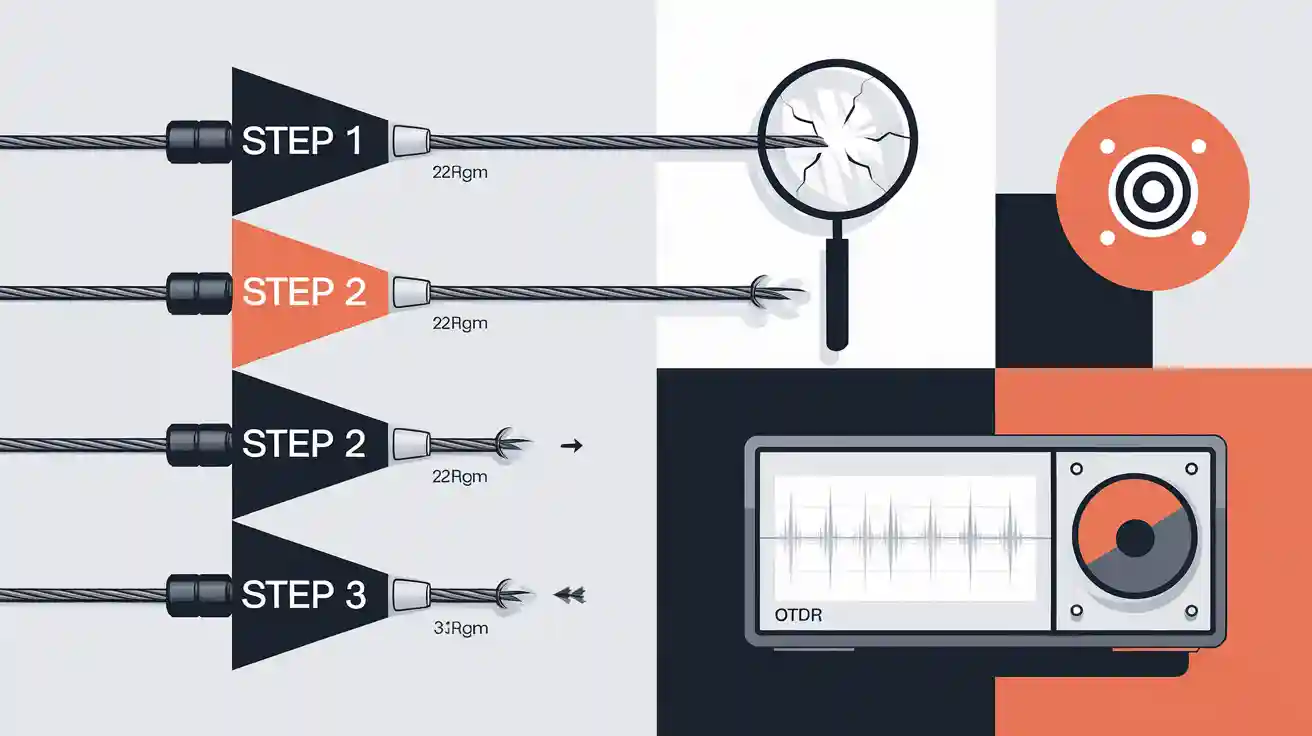
Step 1: OTDR Testing Preparation
Equipment Setup
OTDR Parameter Configuration
You start by configuring your optical time domain reflectometer for accurate fault location. Set the wavelength to match your fiber type—most single-mode fiber optic cable uses 1310 nm and 1550 nm. Adjust the pulse width: use a narrow pulse for short fiber links and high resolution, or a wider pulse for longer cable runs. FLUKE Networks recommends setting the range just beyond the total fiber length and increasing the average time to reduce noise. Always calibrate your OTDR before testing to ensure reliable results. The accuracy of OTDR measurements depends on correct setup, especially when fibers with different backscatter coefficients connect. Regular calibration and maintenance help you avoid unreliable data and improve network performance.
Launch/Receive Cable Requirements
Use both launch and receive cables to measure the entire fiber and avoid dead zones. Select a launch cable of at least 100 meters, following IEC 61300 standards. Make sure your test jumpers match the fiber core size and connector type of your cable system. This setup lets OTDRs and fault locators analyze attenuation and connector loss at both ends of the fiber optic cable. Always stabilize your optical sources and verify the power meter calibration at each test wavelength.
Fiber Preparation
Connector Cleaning Procedure
Clean all connectors, adapters, and jumpers before OTDR test execution. Use an alcohol wipe or a One-Click Cleaner, as recommended by Corning, to remove dust and oil. Contaminated connectors can disrupt the signal and cause inaccurate results. Proper cleaning ensures OTDRs and fault locators detect true attenuation and faults.
Cable Endface Inspection
Inspect the cable endface with a 400x microscope. Follow IEC 61300-3-35 compliance to check for scratches, pits, or contamination. Inadequate fiber preparation can lead to high splice loss and reflective events, which compromise the accuracy of your OTDR test. A clean, undamaged endface helps you achieve reliable linkmap results and accurate attenuation measurements.
OTDR Test Execution
Test Parameters
Dynamic Range Selection
You need to select the dynamic range for your OTDR before you begin troubleshooting in the field. Dynamic range determines how far the OTDR can detect events and faults in the fiber. For most fiber optic cable installations, calculate the total link loss and add a 5 dB margin. This ensures the OTDR can see all events, including breaks and high attenuation points. The table below summarizes key OTDR test parameters that influence fault detection accuracy:
Parameter | Description |
|---|---|
Dynamic range | Difference between initial reflected power and noise floor, measured in dB. |
Event dead zone (EDZ) | Minimum distance between two reflective events the OTDR can distinguish. |
Attenuation dead zone (ADZ) | Minimum distance after a reflective or attenuation event for measuring non-reflective events. |
Insertion loss (IL) | Signal loss due to an event on the fiber link, measured in dB. |
Optical return loss (ORL) | Ratio of reflected power to input power at a discontinuity. |
Optical link length | Distance from first connector to end of fiber link, including all events. |
Tool Selection Guide
Choose the right OTDR for your cable testing needs. Handheld OTDRs and fault locators offer portability for field work and quick troubleshooting. Modular OTDRs provide higher dynamic range and advanced linkmap analysis for longer fiber runs. Compare cost and range before selecting your tool. FLUKE Networks recommends matching your OTDR’s specifications to the cable length and attenuation expected in your installation.
Scan Execution
Automated vs Manual Scan
You can run OTDR scans in automated or manual mode. Automated scans simplify testing by adjusting pulse width and range for you, ideal for routine fiber troubleshooting. Manual scans let you fine-tune pulse width to localize connectors and attenuation events more precisely. Adjusting pulse width helps you detect closely spaced faults and minimize dead zones. Always clean and inspect fiber endfaces before testing, as IEC 61300 standards require. For reliable results, perform bidirectional OTDR testing and keep launch and receive cables connected throughout. Use a visual fault locator (VFL) to confirm breaks in short cable segments. OTDRs and fault locators work together to deliver accurate linkmap results and help you maintain fiber health.
Tip: Regular maintenance and proper installation prevent common errors like microbends, cracks, and physical damage in fiber optic cable.
Step 2: OTDR Trace Analysis

Trace Interpretation Basics
Normal Trace Characteristics
When you analyze an OTDR trace, you look for a gradual attenuation slope, which shows the natural loss of signal as light travels through the fiber. The backscatter coefficient helps you understand how much light returns to the OTDR, acting like a radar echo. According to IEC 61300 standards, a healthy fiber link displays minimal insertion loss at connectors and splices, no significant reflective events, and a steady decline in signal strength. The table below summarizes these features:
Feature | Description |
|---|---|
Insertion Loss | Minimal at connectors and splices, indicating good quality connections. |
Reflective Events | Absence of significant reflective events shows proper connections. |
Signal Strength Decline | Gradual decline without sharp spikes or excessive loss events is ideal. |
Identification of Events | Ability to identify connectors, splices, and other events along the fiber link. |
Connection Points | Confirms the number of connections, ensuring they do not exceed loss limits for applications. |
Tip: Comparing your OTDR trace to a baseline trace from installation simplifies results interpretation and helps you spot changes.
Event Types
You encounter two main event types during OTDR trace analysis:
Reflective events: These appear as sharp spikes on the trace. Connectors and mechanical splices often cause them. High spikes may indicate dirty or misaligned connectors.
Non-reflective events: These show as downward dips. Fusion splices and fiber breaks create these features. A sudden drop signals a break in the fiber optic cable.
Common faults include ghosting (repeated peaks), excessive loss (sharp drops), and dead zones (flat sections). You can use a VFL to confirm breaks in short fiber optic cables.
Fault Localization
Distance Calculation
You pinpoint the exact location of a fault by analyzing disruptions in the OTDR trace. The OTDR calculates distance using the time domain principle:Distance = (Speed of Light in Fiber × Time Delay) / 2
Optimizing OTDR settings, such as pulse width and filters, ensures accurate event analysis and fault location.
Bidirectional Testing
Bidirectional testing means you test the fiber from both ends. This method reduces errors and improves accuracy, especially for attenuation and splice loss. OTDRs and fault locators work together to provide reliable linkmap results. You should always compare traces from both directions for the most accurate results.
Step 3: Post-Test Optimization
Result Validation
IEC 61300 Compliance Check
You need to validate your OTDR results to confirm the integrity of your fiber cable installation. IEC 61300 standards require you to check event loss at every connector and splice. You compare measured attenuation values against the maximum allowed loss for each event. Use the OTDR trace to verify that connectors, splices, and cable segments meet these limits. You should also confirm that the attenuation slope remains consistent throughout the fiber link. This process helps you detect hidden faults and ensures reliable network performance.
Cause of Failure | Percentage of Issues |
|---|---|
Dirty or Damaged Optical Connectors | |
Macrobends | 10% |
Other Components (ONT, OLT, Splitters) | 10% |
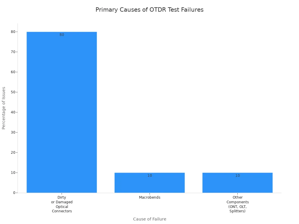
Most failures in the field come from dirty or damaged connectors. You must clean and inspect every cable endface before verification. Macrobends and faulty components also cause attenuation spikes and signal breaks.
Troubleshooting Tips
You improve troubleshooting by understanding radar principles behind OTDRs and fault locators. The OTDR sends light pulses down the cable, then analyzes backscatter to locate faults. You use the backscatter coefficient to identify attenuation changes and pinpoint breaks. For short cable segments, a visual fault locator (VFL) helps you confirm the exact fault location. You should always perform bidirectional verification and compare results to baseline traces.
Tip: Maintain detailed records of every OTDR test. Accurate documentation supports future verification and helps you track cable health over time.
Recommendation | Description |
|---|---|
Maintain detailed records | Keeping comprehensive records of all OTDR tests aids in future reference and helps identify trends or recurring issues within the fiber network. |
Accurate reporting | Ensures installations are verified, faults are documented, and results are traceable for future reference. Detailed reports are essential for identifying fault locations and comparing historical data to spot degradation over time. |
OTDR traces help pinpoint fault locations, verify loss trends, and detect intermittent issues by comparing previous test results. |
You optimize fiber network health by following these steps:
Regular testing of every cable link
Maintenance of OTDRs and fault locators
Thorough documentation of results and verification actions
These practices help you maintain low attenuation, prevent faults, and ensure reliable cable performance.
You master OTDR fault location by following three steps: setup, testing, and trace analysis. You improve troubleshooting in the field and maintain network reliability. Automated testing for fast results helps you detect attenuation and pinpoint fault location. Reference baseline OTDR traces to monitor attenuation and identify gradual fiber degradation.
Baseline traces let you compare attenuation and location changes over time.
Regular testing reveals network trends and predicts future faults.
Ongoing practice with OTDR fault location ensures strong network performance and long-term fiber health.
 Fiber Optic Termination Boxes
 Fiber Optic Splice Enclosures
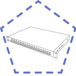 Fiber Patch Panels
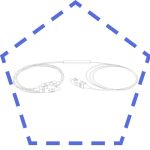 PLC Splitters
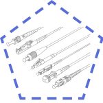 Fiber Optic Pigtails
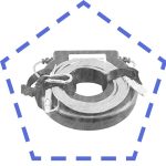 OTDR Launch Cables
 Fiber Optic Adapters
 Fiber Optic Patch Cords